Led Bulb Schematic Diagram
Led Bulb Schematic Diagram
LED bulbs have become increasingly popular in recent years, replacing traditional incandescent and fluorescent bulbs in residential and commercial settings. Although LEDs are more energy efficient and last longer than traditional bulbs, they require a specific circuit to operate properly. This article will provide step-by-step instructions on how to make an LED bulb circuit from scratch.Before.

Led Light Bulb Schematic Wiring Diagram Schemas
LED Light-Emitting Diode (LED) Design Guide Table of Contents Page Introduction 3-4 Safety and Reliability of LED Bulbs 5-7 Surge Immunity Requirements for Consumer LED Lighting/ Retrofit Lamps 8-10 Part Selection Matrix for LED Lamp Protection 11 LED Lighting Compliance with Global Standards 12-15 Part Selection Guide 16-17

Led Light Bulb Schematic Wiring Diagram Schemas
Bob Lory • September 13, 2022 FACTS CHECKED BY Bob Smith LED bulb circuit is the lighting technology that fast replaces incandescent bulbs and fluorescent lamps due to their high efficiency in energy emission. Currently, you can get a LED lamp with 250 lumens per watt (Lm/W) efficiency.
Philips Led Tube Light Wiring Diagram Wiring Diagram Schemas
How-To • LEDs • LEDs 101 Wiring LEDs Correctly: Series & Parallel Circuits Explained! May 27, 2022 by Brooke Sault 586,504 Views Hopefully, those looking for practical information on electrical circuits and wiring LED components found this guide first.
Rechargeable Led Bulb Circuit Diagram
Free Shipping On Orders Over $99. Order LED Light Bulbs Online Today!
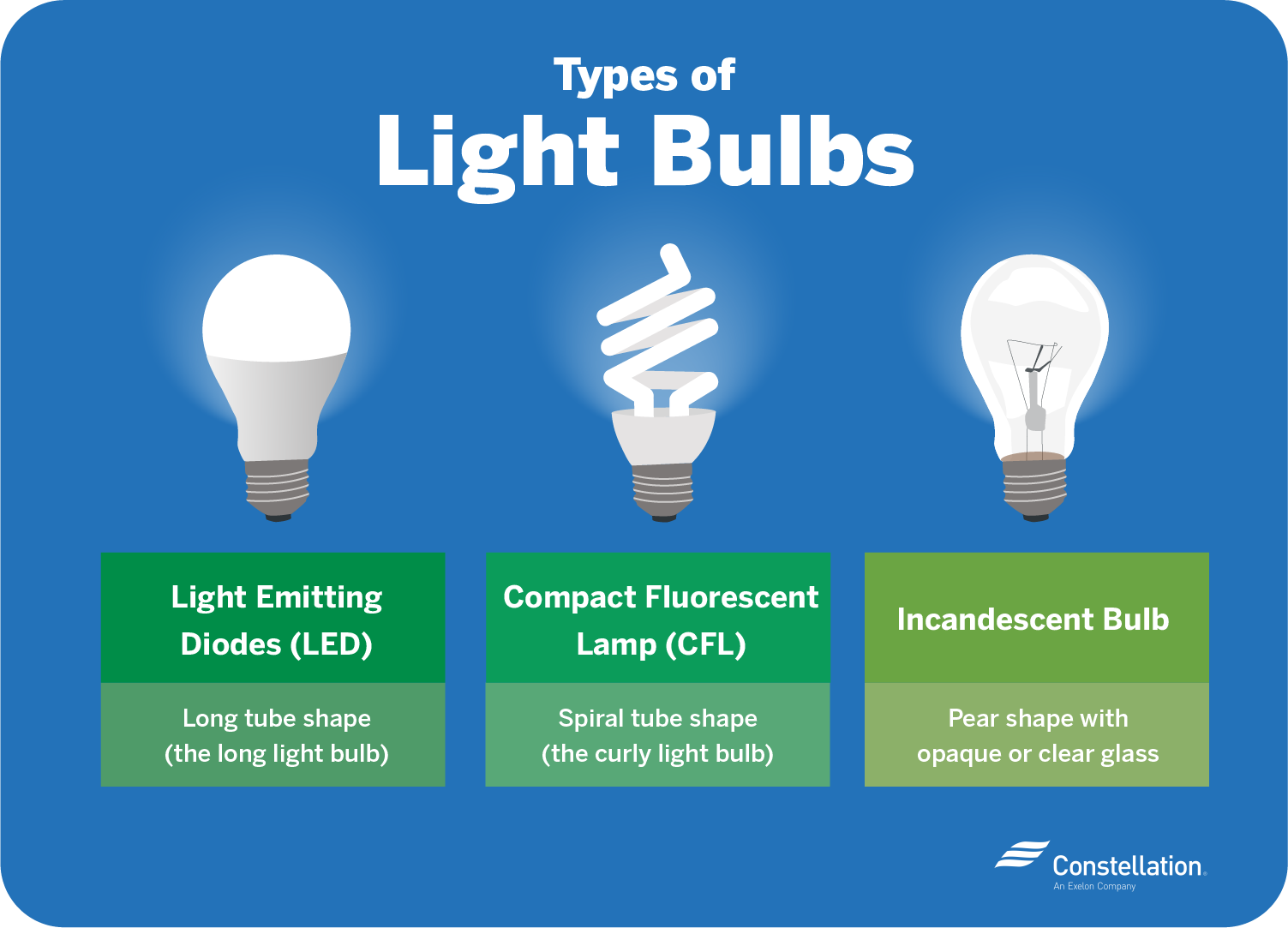
LED vs. CFL Bulbs Which Is More EnergyEfficient?
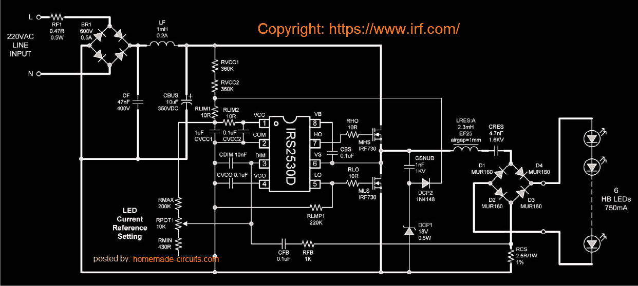
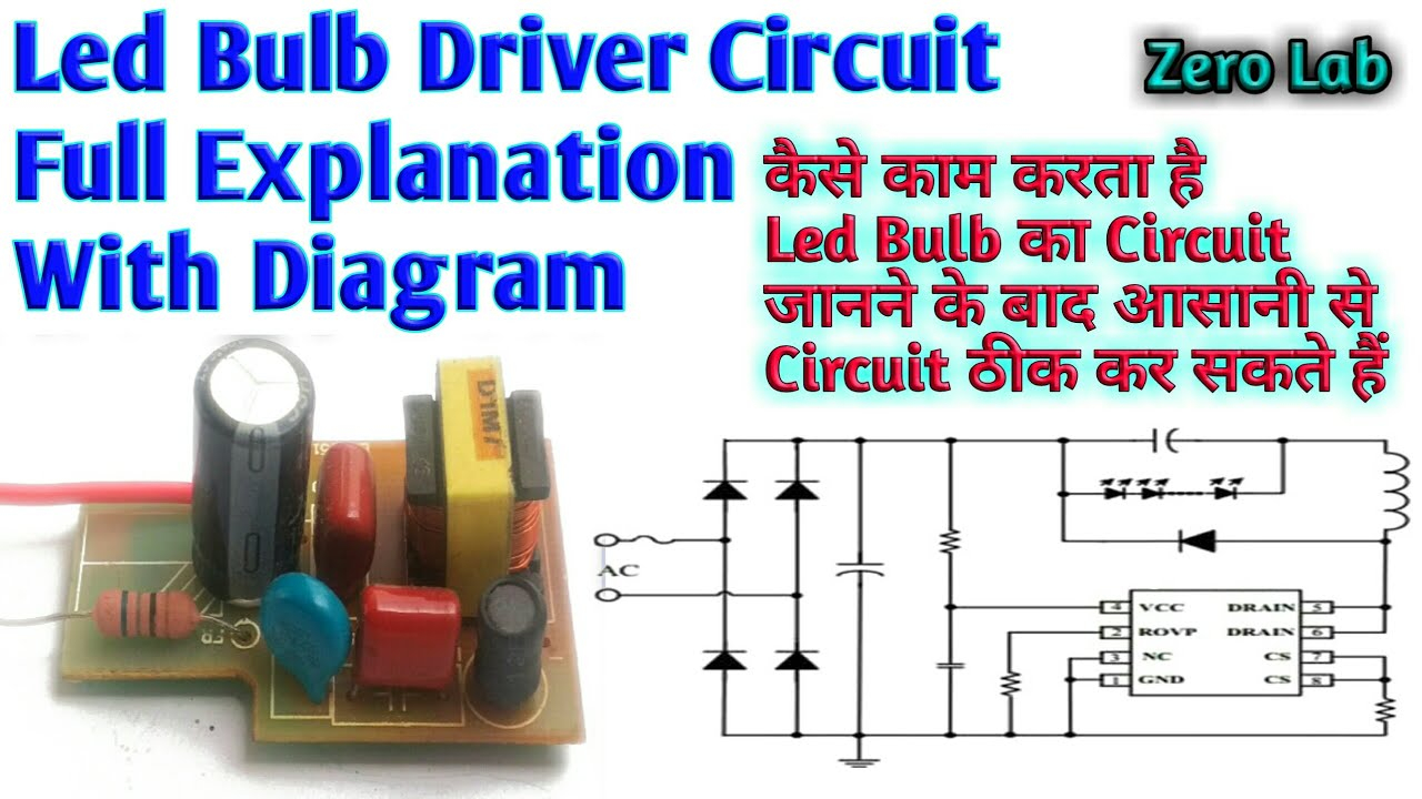
12W LED Light Bulb Schematic Schematic diagram of a 12w 220V LED light bulb made by Star Light: Fig. 1: Schematic diagram of the 12W LED light bulb The heart of the circuit is a PT4554D high precision non-isolated step-down LED constant current IC.

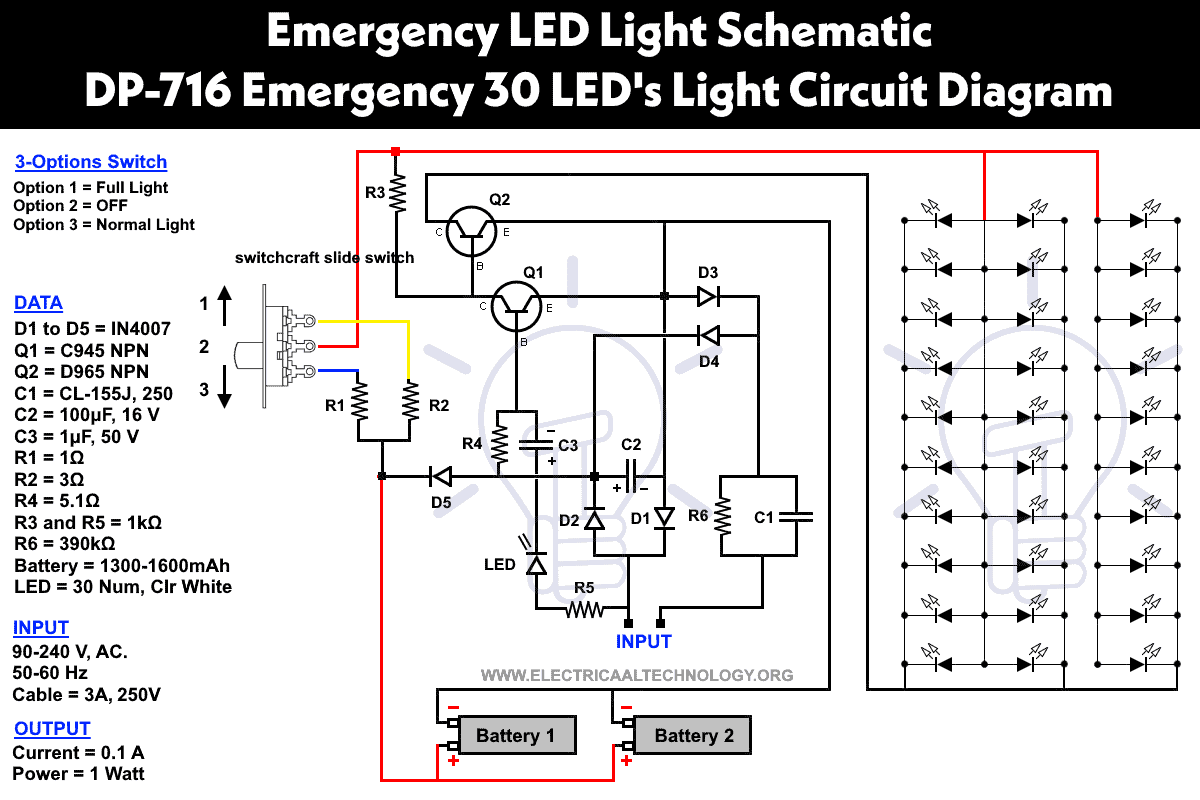
Dp Led 714 Circuit Diagram
In electronics, an LED circuit or LED driver is an electrical circuit used to power a light-emitting diode (LED). The circuit must provide sufficient current to light the LED at the required brightness, but must limit the current to prevent damaging the LED.
Light Bulb Circuit Schematic Wiring Diagram Schemas
Step 1: 3 Volt Basic LED Circuit With 10 Ohms Resistor. The above diagram shows a 3V LED circuit, in this circuit there are two AA cells are used. When you are operating an LED with 3V you have to use minimum 10 ohms resistor . For more details visit Simple Basic LED Circuit Ask Question Step 2: 6 Volt Basic LED Circuit With 390 Ohms Resistor.

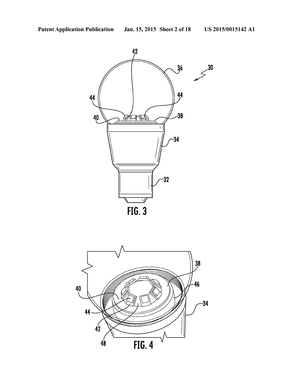
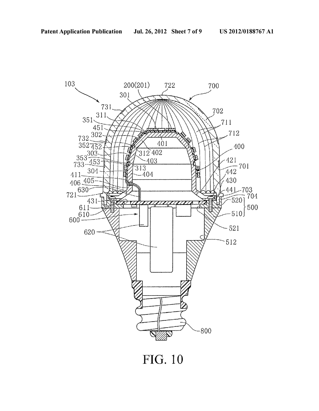
Patent US8227962 LED light bulb having an LED light engine with illuminated curved surfaces
Created on: 30 July 2012 The LED (Light Emitting Diode) is exactly what it name suggests - a diode that emits light. LEDs are like small light bulbs and are available in different sizes and colours. Examples of LEDs used in Electronics LED Symbol The symbol for an LED used in circuit diagrams is shown here: LED Polarity

Circuit Diagram Of Led Lamp
It is very similar to a flashlight - it has a large heatsink, and 1 or more LEDs inside of it (brand and specs of emitters, I do not know). The part that I am most curious about is how the electricity from the socket gets to the emitter. In a flashlight the power comes from a DC battery through a current regulator (LED driver) and into the LED.
Diwali Light Circuit Diagram
Light-emitting diode (LED) technology has revolutionized the lighting industry, providing efficient and long-lasting lighting solutions. Philips, a leading manufacturer in the lighting industry, has developed a range of LED bulbs that are not only energy-efficient but also offer excellent lighting quality.

Led Light Bulbs Circuit Diagram Science and Education
LEDs (that's "ell-ee-dees") are a particular type of diode that convert electrical energy into light. In fact, LED stands for "Light Emitting Diode." (It does what it says on the tin!) And this is reflected in the similarity between the diode and LED schematic symbols: In short, LEDs are like tiny lightbulbs.
Led Light Bulb Schematic Wiring Diagram Schemas
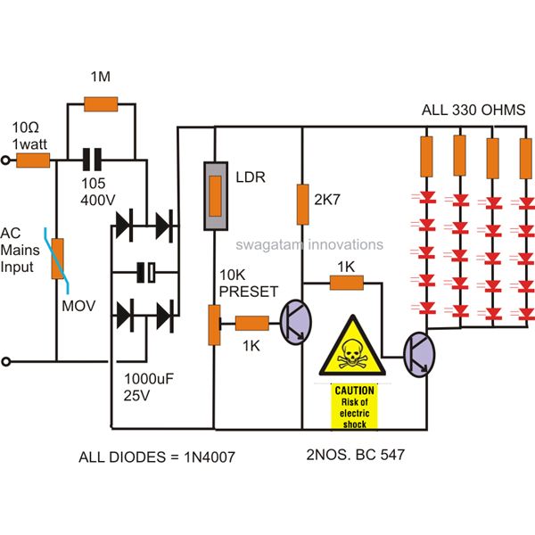
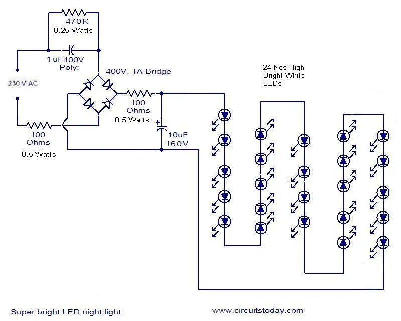
Here we are discussing the making of a simple LED bulb CIRCUIT DIAGRAM, By the word "bulb" we mean the shape of the unit and the fitting secs will be similar to that of an ordinary incandescent bulb, but actually the whole body of the "bulb" would involve discrete LEDs fitted in rows over a cylindrical housing.
Led Light Bulb Schematic Wiring Diagram Schemas
Assuming that a single green LED with 10mA forward current should have a constant operating voltage of 5V, the series resistor R V equals (5V -V F,10mA )/10mA = 300Ω. The forward voltage is 2V, as indicated by a graph of typical operating conditions found in the data sheet (Figure 2). Figure 1. Standard red, green, and yellow LEDs have forward.
Lamp Circuit Diagram / IC555 based Multicolor LED Lamp Circuit Diagram We did not find results
The schematic of an LED light bulb based on voltage is designed to optimize this process and ensure maximum efficiency. The bulb consists of a diode, a driver, and a heat sink. The diode is the heart of the bulb, responsible for emitting light. The driver regulates the amount of voltage and current supplied to the diode, ensuring that it.
100 Watt Equivalent Daylight Led Light Bulb taylormyersdesign
Heat Sink: A small metal board which holds the LED chips and works to direct heat away from the chip during the process of producing light. LED Chips: A small chip which creates the illumination. They are usually yellow and are connected to the metal of the circuit. Know the anatomy of an LED light bulb with our fun infographic.
